For handheld microphones, many sound quality issues originate not from the diaphragm, but from electromagnetic interference. When the internal housing lacks effective EMI/RFI shielding, RF noise from Wi-Fi, mobile phone signals, and LED driver circuits can couple directly into the audio signal chain, causing hum, popping sounds, or intermittent signal loss.
Why EMI/RFI Issues Are Harder to Manage Today Than Before
Ten years ago, a wireless handheld microphone mainly had to deal with interference from UHF TV broadcasts and a limited number of Wi-Fi signals. Today’s live performance environments are completely different:
- 5G smartphones in the audience’s pockets operating on Sub-6GHz frequency bands.
- PWM LED drivers in stage lighting systems, with switching frequencies typically ranging from 50kHz to 1MHz and harmonics that can extend into the hundreds of MHz.
- Multiple wireless systems operating on the same stage, including IEMs, bodypack transmitters, and wireless camera video links.
- Densely deployed Wi‑Fi 6/6E access points inside the venue(2.4GHz / 5GHz / 6GHz)
In modern live performance environments, RF spectrum congestion has far exceeded what it was a decade ago, and one of the main causes of signal dropouts is broadband radiated interference from non-audio devices.
This means that enclosure shielding design is no longer a “nice-to-have,” but a fundamental part of baseline reliability.
Basic Principles of Electromagnetic Shielding
Before discussing materials and structures, it is necessary to distinguish between two types of interference mechanisms, because they require different mitigation approaches:
Electric-field interference (E-field / RFI)
- Primarily propagates through capacitive coupling
- Can be effectively shielded by high-conductivity materials (such as copper and aluminum)
- Grounding is critical — an ungrounded shielding layer is effectively no shielding at all
Magnetic-field interference (H-field / low-frequency EMI)
- Primarily propagates through inductive coupling, commonly seen at 50/60 Hz power frequency and its harmonics
- Effective attenuation requires high-permeability materials (such as permalloy and mu-metal)
- Copper and aluminum provide limited shielding effectiveness against low-frequency magnetic fields
Shielding Effectiveness (SE) is expressed in dB; the higher the value, the stronger the attenuation. In general engineering practice:
| item | Protection level | Application scenarios |
|---|---|---|
| SE≥40dB | Basic protection | Suitable for low-interference environments |
| SE≥60dB | Medium protection | Suitable for most performance scenarios |
| SE≥80dB | High protection | Suitable for broadcast-grade or medical-grade applications |
Comparison of Major Shielding Materials
Copper Foil
Copper is the most commonly used shielding material inside handheld microphones, for straightforward reasons: high electrical conductivity, solderability, and reliable grounding connections.
- In the 1MHz–1GHz frequency range, copper foil typically provides shielding effectiveness of about 85-100dB
- According to the product specifications of 3M 1181 copper foil tape, its transfer impedance at 1GHz is extremely low, making it suitable for high-frequency RFI protection.
- Main limitation: relatively weak shielding performance against low-frequency magnetic fields below 1kHz.
(source:3M, “EMI Copper Foil Shielding Tape 1181 Data Sheet”, https://multimedia.3m.com/mws/media/37370O/3m-emi-copper-foil-shielding-tape-1181-data-sheet-78-8127-9953-0-b.pdf)
When applying copper foil to the inner wall of the enclosure, note the following:
- The copper foil must form a low-impedance connection to the enclosure grounding point; otherwise, shielding performance will be significantly reduced.
- Seams should have sufficient overlap width (recommended≥6mm) to prevent leakage through gaps.
- Copper foil thickness is typically selected in the range of 0.05–0.1mm; if too thick, it increases weight, while if too thin, mechanical strength may be insufficient.
Aluminum Foil and Aluminum Alloy Enclosures
Aluminum has a conductivity of about 61% that of copper. Its shielding effectiveness is slightly lower, but it is lighter and more cost-effective.
- In the high-frequency range (>10MHz), aluminum foil typically provides shielding effectiveness of around 60–80dB, which is sufficient for most RFI scenarios.
- Die-cast aluminum alloy enclosures inherently provide a certain level of shielding. However, note that anodizing forms an insulating surface layer that disrupts electrical continuity. During assembly, conductive treatment is required at contact surfaces.
Mu-Metal (Permalloy)
This is a shielding material specifically designed for low-frequency magnetic fields. Its relative permeability (μr) can reach 20,000–100,000, far higher than copper (μr≈1).
- Typical use case: microphones operating in strong power-frequency magnetic field environments (such as near transformers or high-power audio amplifiers).
- In practical applications, mu-metal is usually used as thin sheets wrapped around the microphone capsule or the preamplifier module.
- It is relatively expensive, and annealing is required to achieve maximum permeability. Strong bending during processing should be avoided.
Conductive Coating
For plastic enclosures, conductive coatings are the primary means of achieving shielding:
- Common types: silver-based conductive paint, copper-based conductive paint, and nickel-based conductive paint.
- Silver-based coatings have the highest conductivity but are costly; nickel-based coatings offer good corrosion resistance with moderate cost.
- Coating thickness is typically 10–25μm, and shielding effectiveness (SE) can reach 40–60dB (depending on frequency and coating uniformity).
- Key issue: how the coating is connected to ground—if it is only sprayed on without a reliable grounding path, the shielding effect will be very limited.
Structural Design Essentials for Handheld Microphone Housings
Grounding Path Design
This is the most commonly overlooked—and most failure-prone—part of the entire shielding system.
The purpose of the shielding layer is to drain induced interference current away, not let it enter the signal chain. That drainage route is the grounding path.
Common design mistakes:
- The shielding layer is connected to the PCB ground point through a thin wire; if the wire is too long (>5cm), high-frequency impedance becomes too high, and shielding performance drops sharply above 100MHz.
- Metal housing parts are joined by threaded connections, but oxidation on the thread contact surfaces creates high-impedance contact.
- There is a discontinuity between the microphone head shield and the handle shielding layer, creating an “antenna effect.”
Correct practices:
- Keep the grounding path as short and direct as possible; use wide copper straps instead of thin wires.
- Apply conductive treatment on metal contact surfaces (e.g., conductive gaskets or spring contacts).
- Maintain shielding-layer continuity along the full housing length, with no breaks.
Aperture and Gap Management
Any opening or gap is a weak point in the shielding layer. A practical rule of thumb is: the maximum gap size should be less than 1/20 of the wavelength of the highest interference frequency.
Using 2.4GHz Wi-Fi as an example, the wavelength is about 125mm, and 1/20 is approximately 6.25mm. This means any enclosure gap larger than 6mm will cause noticeable leakage in the 2.4GHz band.
Key areas to address in real designs:
- Connection between the microphone head and handle: this is usually a threaded joint, so gaps are unavoidable; add internal conductive spring fingers or conductive foam.
- Switch/button openings: use conductive padding around button apertures.
- Battery compartment cover: if the battery compartment is inside the handle, conductive continuity of the cover must be specifically designed.
- Audio output connector (XLR/TRS): the connector’s metal shell must be reliably bonded to the overall shielding layer.
PCB-Level Shielding
Enclosure shielding addresses the issue of external interference entering the system, but the microphone’s internal PCB can also be an interference source (especially the wireless transmitter module).
For wireless handheld microphones, PCB-level shielding/EMC measures include:
- Physical isolation between the RF module and audio preamplifier circuitry (metal shielding can).
- Power-line filtering (LC filters to suppress switching power noise).
- Keeping analog signal traces away from digital traces to reduce crosstalk.
- Local shielding cans over critical analog circuits (microphone preamplifier).
In EMC optimization of wireless microphone PCBs, isolation between the RF module and audio circuitry is one of the core measures for reducing internal interference.
A noteworthy real-world case:
During a customer collaboration, we encountered the following issue: a certain brand of UHF wireless handheld microphone received reports from the European market of intermittent popping noise in specific venues, while factory testing showed no problems at all.
Troubleshooting revealed that the issue was caused by a shielding discontinuity at the joint between the microphone head and the handle. The venue used a large number of DMX-controlled LED fixtures, whose driver circuits generated broadband radiation with significant energy in the 400–600MHz range—right near the operating band of that wireless system.
ffectively acted as a small receiving antenna in that frequency range, coupling interference directly into the audio preamplifier.
The fix was to add a ring of conductive silicone sealing strip at the joint to restore shielding continuity across the gap. The problem disappeared immediately. This case shows that shielding design details often determine real-world product performance in complex electromagnetic environments.
Design Checklist
Before finalizing the enclosure design, it is worth confirming the following items one by one:
Material Selection
- Has the shielding material been selected based on the primary interference frequency band (copper/aluminum for high-frequency RFI, mu-metal for low-frequency magnetic fields)
- Does the conductive coating on the plastic enclosure have uniform coverage, and does its thickness meet specifications
Grounding Continuity
- Does the shielding layer have a clearly defined low-impedance grounding path
- Have conductive treatments been applied to contact surfaces between metal parts
- Is the grounding wire length controlled within a reasonable range (for high-frequency applications, <3cm is recommended)?
Gap Control
- Are all openings and gaps smaller than 1/20 of the wavelength of the highest interference frequency?
- Are conductive sealing measures in place at the microphone head–handle connection?
- Are conductive gaskets used for button openings and the battery compartment cover?
Internal Isolation
- Is there physical isolation between the RF module and the audio circuitry?
- Is there sufficient filtering on the power lines?
Our Observation
From an enclosure manufacturing perspective, EMI/RFI shielding failures are rarely caused by choosing the wrong material; more often, they result from overlooking two details: grounding paths and gap management.
A copper foil with SE=80dB, if poorly grounded, may deliver worse real-world shielding than an aluminum-alloy enclosure with only SE=50dB but reliable grounding. Material performance defines the upper limit, while structural design determines actual performance.
For assembly factories and brand owners, fully communicating shielding requirements with the manufacturer during the enclosure design phase is far more efficient than making corrective fixes after product finalization. If you are developing a new handheld microphone product, feel free to discuss specific enclosure shielding solutions with our engineering team.
About ENPING SHUNFENG ELECTRONICS CO., LTD
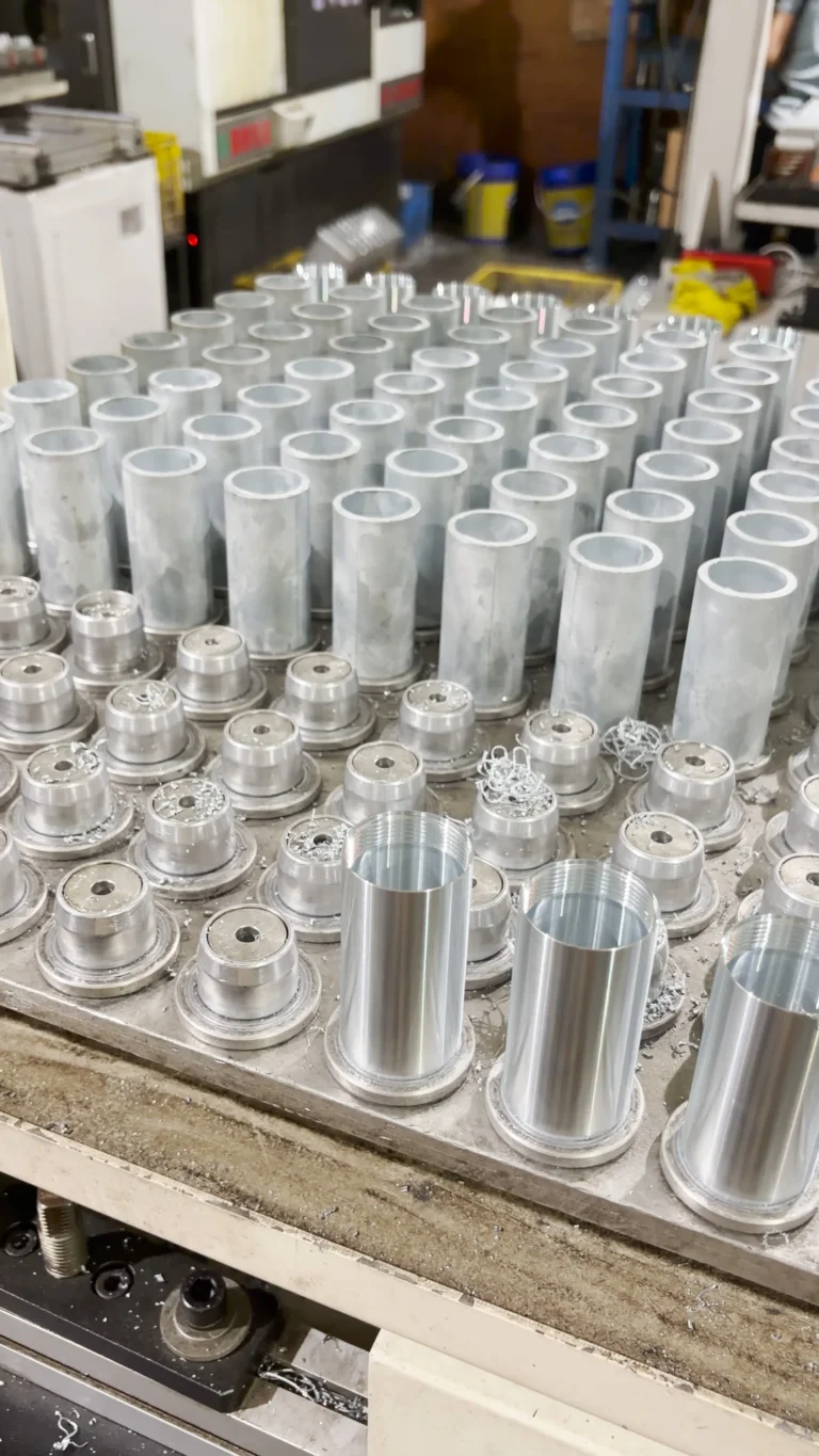
We are a factory focused on handheld microphone enclosure manufacturing, with 20 years of industry experience, serving microphone assembly factories and brands worldwide. If you would like to learn more about enclosure shielding design solutions or custom services, please contact our technical team.