Paint rarely peels from a microphone body because of “bad paint” alone. More often, the visible failure is the final result of a broken manufacturing chain: oil remained on the metal, the pretreatment did not match the alloy, gas escaped from a die casting during cure, the coating was under-cured, or assembly concentrated stress at an edge or thread.
For a microphone brand, this is more than a cosmetic defect. A handheld housing is repeatedly exposed to grip friction, perspiration, cosmetics, cleaning products, transport, and assembly. In Southeast Asian distribution and use, persistent heat and humidity can further expose weak pretreatment, damaged edges, or coating pores. Singapore's official climate data, for example, reports mean annual relative humidity of about 82%. Humidity does not make a properly specified coating spontaneously peel, but it can accelerate corrosion or blistering after moisture reaches a weak interface.
The practical solution is to control the housing as a substrate–pretreatment–coating system, then verify that system on production-representative parts before mass production.
Start with the Failure Pattern
“Peeling” can describe several different defects. The location and appearance of the failure often provide the first useful clue.
| What you see | Likely mechanism to investigate first | Why it matters |
|---|---|---|
| Coating lifts in sheets and reveals clean bare metal | Inadequate cleaning, unsuitable pretreatment, or poor adhesion at the metal interface | The coating may look acceptable at inspection but has never bonded reliably |
| Bubbles, pinholes, or raised blisters | Moisture, trapped chemicals, or outgassing from a porous casting | The defect may create a path for later corrosion and wider delamination |
| Chips around button holes, grille joints, or end-cap edges | Sharp geometry, burrs, thin edge coverage, impact, or assembly interference | Local mechanical stress may exceed the coating's tolerance |
| Paint cracks or tears at threads | Excess film build, unmasked functional surfaces, insufficient thread allowance, or repeated metal-to-metal contact at threaded interfaces | A cosmetic problem can become an assembly and fit problem |
| Top layer separates but the primer remains | Intercoat contamination, incompatible layers, or an incorrect recoat/cure window | The weak interface is within the coating system rather than at the metal |
| Failure appears after humid storage or shipping | Exposed substrate, soluble contamination, weak conversion layer, or inadequate packaging should be investigated | The environment often reveals an existing weakness rather than creating it alone |
A supplier should not respond to every pattern by simply increasing paint thickness. More coating can worsen fit at threads and cutouts, trap more stress at edges, or hide rather than solve a contaminated interface.
Seven Common Causes of Paint Peeling from Metal Microphone Bodies
1. Oil, polishing compound, dust, or fingerprints remain on the surface
Die release agent, cutting fluid, polishing compound, and handling contamination can all prevent a coating from wetting or bonding to the metal. A visually clean housing is not necessarily chemically clean. Deep holes, internal shoulders, and threaded areas are especially easy places for cleaner, water, or process residue to remain.
Cleaning therefore needs defined bath condition, concentration, time, temperature, rinsing, drying, and handling—not an informal wipe immediately before spraying.
2. Pretreatment does not match the substrate
Zinc alloy, aluminum alloy, steel, and brass do not present the same surface chemistry. A process that works on one substrate cannot automatically be copied to another. The conversion layer or primer must be compatible with the actual alloy, coating system, and environmental requirement.
This is why the drawing and RFQ should identify the base material rather than specify only a color such as “matte black.” If the substrate changes after sample approval, the finish process needs to be revalidated.
3. A die casting releases gas during cure
Zinc and aluminum die castings can contain porosity or trapped process residue. When a part is heated for baking or powder-coat cure, gas can move toward the surface and form pinholes, craters, or blisters. Industry troubleshooting guides identify casting materials and zinc surfaces as common outgassing sources and list controlled preheating or suitable additives among possible countermeasures.
Pre-baking is not a universal recipe. Its time and temperature must be validated against the alloy, casting, coating chemistry, and dimensional or cosmetic requirements. The better approach begins earlier: manage casting quality, avoid excess release agent, clean the part correctly, and trial the complete finish cycle on production-representative castings.
4. The coating does not reach its specified cure window
An oven setpoint is not the same as the temperature reached by the part. Housing mass, rack density, airflow, loading pattern, and line speed all affect the actual cure history. Under-cure can reduce film properties; excessive heat can also create defects or damage a sensitive substrate or coating system.
Manufacturers should establish a validated cure schedule for the part and coating combination and control repeat production against it. A change in housing wall thickness or rack loading may justify another check.
5. Film thickness is uneven or inappropriate
Thin coverage at sharp edges leaves less protection. Heavy buildup in recesses, holes, and threaded interfaces can crack, bridge, interfere with assembly, or create an obvious witness mark when compressed.
The print should distinguish:
- Class-A visible surfaces
- Areas where coating thickness is functionally limited
- Masked threads or grounding contacts
- Cut edges and hole boundaries that require particular attention
- Surfaces where color and gloss are judged against an approved master sample
6. Part design or assembly damages an otherwise acceptable finish
A coating cannot compensate for burrs, knife edges, interference fits, or a tool that contacts a visible surface during assembly. Button openings, battery doors, grille joints, end caps, and threaded connections deserve a coating-clearance review during DFM.
Useful questions include:
- Does the mating-part clearance include the coating stack?
- Should a thread or grounding land be masked?
- Are visible edges rounded enough to support consistent coverage?
- Can the assembly fixture avoid Class-A surfaces?
- Will repeated battery changes or grille removal rub the same edge?
If peeling is concentrated at one geometry, changing paint chemistry before checking the design may waste time.
7. The finish specification does not match real use
“Black paint” is not a durability requirement. A wireless handheld microphone for rental stages, karaoke venues, hospitality sites, or frequent shared use may encounter abrasion, sweat, skin oils, cosmetics, and alcohol-based cleaning. Storage and distribution may add heat, humidity, condensation, or salt-bearing coastal air.
The buyer should define the actual exposure and then agree on relevant tests. A salt-spray duration copied from an unrelated outdoor product is not automatically meaningful for a microphone. Test method, specimen, scribe condition, duration, conditioning, evaluation area, and pass/fail criteria all need agreement.
Zinc Alloy vs. Aluminum: Why the Same Paint Process May Not Work
| Housing substrate/process | Advantages for microphone housings | Coating risks to manage | Useful controls |
|---|---|---|---|
| Zinc-alloy die casting | Complex shapes, integrated features, and a substantial hand feel | Release-agent contamination, porosity, outgassing, and substrate-specific pretreatment | Casting and lubricant control, substrate-compatible pretreatment, representative cure trials, inspection for pinholes and blisters |
| Aluminum extrusion or CNC machining | Low weight, clean cylindrical geometry, and good machining potential | Cutting-fluid residue, native oxide condition, sharp machined edges, and finish compatibility | Thorough cleaning, controlled surface preparation, edge review, agreed conversion or anodizing route, coating-clearance check |
| Aluminum die casting | Lightweight complex geometry | Both casting-related porosity/outgassing and aluminum-specific pretreatment requirements | Casting control plus a validated aluminum pretreatment and cure cycle |
| Steel or brass components | Useful for selected grilles, rings, or structural details | Different corrosion behavior and pretreatment needs; mixed-metal assemblies can introduce additional interfaces | Specify every material, isolate or protect interfaces where necessary, and validate the complete assembled system |
Material choice should be made together with weight, geometry, RF/grounding design, tooling, machining, cosmetic target, and production volume. “Which metal takes paint best?” is less useful than “Which complete material and finish system meets this product's requirements with repeatable production control?”
How Manufacturers Prevent Peeling Before Mass Production
Step 1: Convert appearance language into an engineering specification
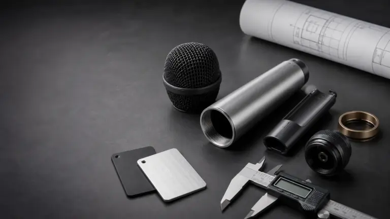
Begin with substrate and process, coating type, color reference, gloss or texture range, visible-surface classification, masking, acceptable defect limits, intended environment, and required tests. Add drawings or annotated renderings to show where appearance is critical.
An approved sample is valuable, but it should support—not replace—written criteria. Samples can fade, become damaged, or be interpreted differently by purchasing, engineering, and inspection teams.
Step 2: Review the design for finishing and assembly
Before tooling a microphone housing, review drainage, blind holes, hanging points, recesses, sharp edges, thread allowance, grounding contacts, and assembly-tool access. Determine where the part can be held during pretreatment and spraying without creating an unacceptable rack mark.
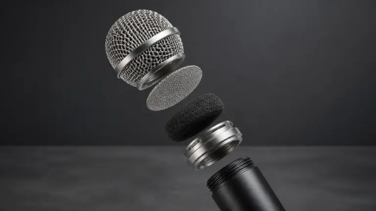
This review is especially important for a full housing set. A tube may pass finish inspection on its own and still chip when assembled with the grille, switch frame, battery cover, or end cap.
Step 3: Stabilize the substrate
Control casting condition or machining condition before finishing. The finishing line should not be expected to hide severe porosity, deep tool marks, burrs, or inconsistent polishing. If a change in release agent, cutting fluid, alloy, supplier, or machining route can affect the surface, it belongs in change control.
Step 4: Clean, pretreat, rinse, and dry consistently
Pretreatment is a process, not a product name. The manufacturer should manage the parameters recommended for the selected chemistry and verify that complex parts drain and dry. Recontamination between pretreatment and coating must also be prevented.
Step 5: Apply and cure the agreed coating system
Spray coverage, electrostatic behavior, part orientation, film build, flash-off where relevant, oven loading, and cure all influence the result. First-article trials should use the intended substrate and realistic rack loading rather than a flat laboratory coupon alone.
Step 6: Validate appearance, adhesion, and use-related durability
ISO 2409:2020 defines a cross-cut method that assesses a coating's resistance to separation after a lattice is cut through to the substrate. ASTM D3359-23 provides tape-test methods for relatively ductile coatings on metal. Both are comparative or classification tools, not direct measurements of absolute bond strength.
For a microphone housing, the verification plan may also include:
- Dry-film thickness at agreed measurement locations
- Visual inspection under defined lighting and viewing distance
- Cure verification appropriate to the coating supplier's system
- Assembly and repeated-use checks at threads, covers, switches, and end caps
- Abrasion or handling simulation
- Resistance to specified cleaning agents, artificial perspiration, or cosmetics
- Humidity, cyclic corrosion, or salt-spray testing where the product's use and risk justify it
The buyer and manufacturer should agree on the method, conditioning, sample count, rating, and acceptance threshold. Writing only “must pass adhesion test” is incomplete.
Step 7: Protect the finish during assembly and shipping
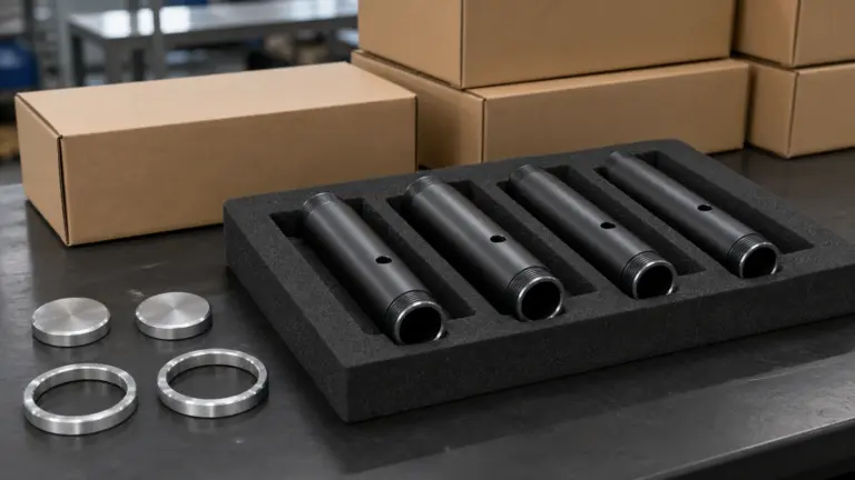
Clean gloves, non-marking fixtures, separated parts, controlled packaging contact, and dry storage help preserve the approved finish. Packaging should be trialed with the real coating because some foams, films, adhesives, or trapped moisture can mark or attack a surface during warm storage.
For Southeast Asian shipments, the packaging review should consider long, humid logistics routes and temperature cycling. The solution should be selected for the actual coating and product; it should not be assumed that one desiccant or protective film is compatible with every decorative finish.
What to Put in a Microphone Housing RFQ
Use this checklist to obtain comparable quotations and reduce disputes after sample approval:
- Part number, revision, 2D drawing, and 3D model
- Base material, alloy or grade, and forming/manufacturing process
- Visible-surface map and cosmetic acceptance standard
- Coating system or performance requirement—not color alone
- Color standard, gloss range, texture, and approved-master process
- Target thickness or functional maximum where relevant
- Masking requirements for threads, grounding points, and mating surfaces
- Assembly interfaces and coating-inclusive clearances
- Expected exposure to sweat, cleaners, cosmetics, humidity, and coastal conditions
- Required test standards, methods, sample count, conditioning, and pass/fail grade
- First-article and golden-sample approval process
- Batch documentation, change-control, packaging, and defect-handling expectations
Also send the mating parts when possible. A housing supplier can judge coating buildup and contact risk more accurately from a trial assembly than from an isolated tube drawing.
A Better Finish Starts Before the Spray Booth
Durable paint on a microphone body depends on aligned decisions from DFM through shipping. Cleaning and pretreatment create the interface; casting and machining determine the condition below it; coating and cure form the protective film; geometry, assembly, and packaging determine how that film is stressed.
Micbody manufactures custom microphone housings and metal components in zinc alloy, aluminum alloy, and brass, with support from prototyping and tooling through die casting, CNC machining, laser cutting, surface finishing, and mass production. Send your 2D/3D drawings, target finish, mating-part details, operating environment, and acceptance criteria for a manufacturability review and quotation. Where the finish requirement is not yet measurable, our team can identify the questions that should be resolved before sampling.
FAQ
Can high humidity make paint peel from a microphone body?
Humidity alone should not cause a properly specified and intact coating to peel. It can accelerate failure when moisture reaches the metal through pores, scratches, thin edges, or a weak interface. For products sold in hot, humid regions, define the environment and validate the complete substrate–pretreatment–coating system rather than simply requesting “weather-resistant paint.”
Is powder coating always more durable than liquid paint on a microphone housing?
No. Durability depends on the substrate, pretreatment, coating chemistry, film build, cure, geometry, and exposure. Either system can fail if the metal is contaminated or the process is incorrect. Choose the system against measurable cosmetic, chemical, wear, assembly, and environmental requirements.
Why does paint chip first around threads and button holes?
Edges and cutouts may receive thinner coverage and experience higher local stress. Burrs, sharp corners, coating buildup, insufficient assembly clearance, or tool contact can start a chip. Inspect the geometry, masking, film thickness, and assembly process before treating it as a paint-only problem.
What adhesion test should a buyer specify?
ISO 2409 and ASTM D3359 are widely recognized cross-cut/tape-test approaches, but the buyer must name the edition, method or classification, conditioning, locations, sample count, and acceptance threshold. These tests indicate resistance to separation; they do not provide an absolute bond-strength value.
What should I send for a custom microphone housing quotation?
Send 2D and 3D files or a physical sample, the material and finish requirement, target quantity, mating parts or interface dimensions, visible-surface standard, use environment, and test/acceptance criteria. Clear inputs allow the supplier to review both manufacturability and finish risk before mass production.