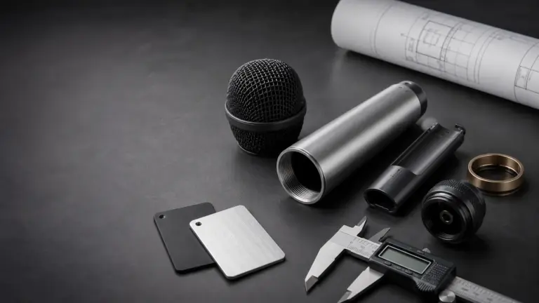
A microphone grille has to let sound reach the capsule while protecting it from drops, fingers, dust, moisture, and repeated handling. It may also support an internal foam layer, complete an electrical shielding path, screw onto the microphone body, and carry the finish that customers see first.
That combination makes grille design a system problem. Choosing “stainless mesh” or copying the dimensions of an existing grille is not a complete specification. The same outer shape can behave differently when the wire diameter, mesh opening, number of layers, internal spacing, foam, seam, finish, or capsule position changes.
For an OEM project, the practical goal is not to maximize protection or open area in isolation. It is to define a grille assembly that meets the microphone's acoustic target, survives its intended use, can be produced consistently, and fits the rest of the housing without rework.
A Microphone Grille Is More Than the Visible Metal Shell
Depending on the microphone architecture, a grille or headbasket can include several functional elements:
- An outer basket, ball, frame, or perforated shell
- One or more layers of woven, expanded, or perforated metal
- Internal acoustic foam, fabric, or another porous layer
- A support ring, collar, thread, bayonet, or press-fit interface
- Welded, crimped, bonded, or mechanically locked joints
- A conductive path to the main housing or circuit ground
- Decorative plating, paint, powder coating, polishing, or another finish
These elements are coupled. A denser inner layer may improve particle protection but add acoustic resistance. A stronger outer mesh may reduce denting but transmit more impact toward the capsule support. A thicker finish may improve appearance while changing thread fit or closing small openings. A grille that passes visual inspection by itself can still fail after assembly because the seam rotates out of position, foam is compressed unevenly, or the head does not seat on the body.
The grille specification should therefore cover both the individual component and the assembled microphone.
Start with Five Design Requirements
| Requirement | Questions for the project team | Typical supplier input |
|---|---|---|
| Acoustic behavior | What frequency response, sensitivity, polar pattern, and plosive behavior must the complete microphone maintain? | Capsule data, reference response, acoustic test method, approved assembly |
| Mechanical protection | What drops, impacts, finger pressure, and transport loads are credible? Is controlled denting acceptable? | Drop orientation, impact locations, capsule clearance, deformation limit |
| Environment and cleaning | Will the product encounter sweat, cosmetics, alcohol-based cleaners, coastal air, or humid storage? | Exposure list, test fluids, conditioning, corrosion and appearance criteria |
| Assembly and service | Is the grille removable? What thread, torque, alignment, grounding, and replacement requirements apply? | Mating parts, interface drawing, torque range, cycle requirement |
| Appearance and production | Which surfaces are Class A? How are color, gloss, seam position, mesh uniformity, and dents judged? | Color standard, master sample, viewing conditions, defect limits |
Purchasing teams should ask for a quotation against this complete requirement set. Otherwise, two suppliers may quote parts that look similar in a rendering but differ substantially in construction, validation, and production risk.
Open Area Matters, but It Is Not a Stand-Alone Acoustic Specification
Open area is the percentage of a mesh surface that is unobstructed. For a square plain weave, it can be estimated from the opening width and wire diameter:
Open area (%) = [opening / (opening + wire diameter)]² × 100
W.S. Tyler's wire-mesh guidance explains that open area changes with opening width, wire diameter, mesh count, and weave type. It also highlights the basic mechanical tradeoff: increasing open area can improve flow, but thinner wire may reduce strength.
For a microphone grille, that percentage is useful for comparing candidate meshes, but it does not predict the complete acoustic result. Two constructions with the same nominal open area may differ because of:
- Wire shape and surface condition
- Plain, twill, expanded, or perforated construction
- One layer versus several offset layers
- Foam or fabric behind the metal
- Distance from the mesh to the capsule
- Enclosed cavity volume and grille shape
- Welds, frames, supports, and local blocked areas
- Paint or plating buildup at the openings
Do not put only “60% open area,” “40 mesh,” or a catalog material name on the drawing. Specify the construction parameters that matter, define how they will be measured, and retain an approved production sample.
Mesh, Foam, and Cavity Geometry Can Change the Acoustic Response
Every layer between the sound source and the microphone diaphragm becomes part of the acoustic path. Knowles' SiSonic Design Guide notes that acoustic-path dimensions and mesh can affect microphone frequency response. Gore's acoustic design guide similarly explains that housing, cavity, protective vent, gasket, PCB path, and microphone placement interact as a system.
Those guides address small microphone ports, but the engineering lesson also applies to handheld and studio microphone grilles: a protective layer cannot be evaluated independently from the volume, spacing, openings, and transducer behind it.
Why additional layers are not automatically better
Multiple mesh and foam layers can help control plosive airflow, particle entry, and direct contact. They can also increase acoustic resistance, introduce cavity effects, retain contamination, or make production variation more difficult to control. Foam density, thickness, compression, pore structure, and position all matter.
The correct layer stack is therefore an acoustic decision as well as a sourcing decision. A housing supplier can manufacture to the agreed construction, but the microphone brand should approve the grille using the intended capsule, mount, foam, body, electronics, and signal processing.
Validate the production assembly, not only a flat material sample
A material coupon can compare mesh or foam candidates, but it does not reproduce the finished grille. Forming changes geometry; seams and support rings block local area; adhesive or welds alter the boundary; and the final distance to the capsule affects the cavity.
At minimum, compare the reference microphone and the proposed production assembly under the same conditions. Relevant characteristics may include sensitivity, frequency response, directional response, plosive behavior, handling noise, and unit-to-unit variation. IEC 60268-4:2018 defines methods for measuring key characteristics of sound-system microphones and can provide a framework where the project requires standardized measurements.
Impact Protection Requires an Intentional Deformation Strategy
A grille is often the first component to contact the floor. “No dent after any drop” may sound like the strongest requirement, but maximum stiffness is not always the best way to protect the capsule. The project team needs to decide where impact energy should go and how much clearance must remain after deformation.
Shure describes the SM58 grille as an impact-absorbing structure designed to dent before the cartridge is damaged. Its grille design explanation is a useful reminder that visible deformation can be an intentional protective behavior rather than an automatic design failure.
This does not mean every grille should dent easily. It means the requirement should be functional and measurable. Consider:
- Minimum clearance between the grille and capsule after the specified impact
- Whether a dent may create a sharp edge or loose wire
- Whether the grille can still be removed and replaced
- Whether the thread, collar, or body is permanently distorted
- Whether foam contacts or loads the capsule after deformation
- Whether the microphone still meets the agreed acoustic and electrical checks
Prototype drops should include realistic orientations: top-first, angled grille impact, side impact near the joint, and impacts that load the thread or collar. Test fixtures and pass/fail criteria should be agreed before comparing suppliers.
Material and Finish Must Match the Product's Real Use
Common grille constructions may use plated steel, stainless steel, aluminum, or combinations of materials. The best choice depends on forming method, wire strength, weight, corrosion exposure, finish, weldability, electrical continuity, and target deformation behavior.
Plated or coated steel
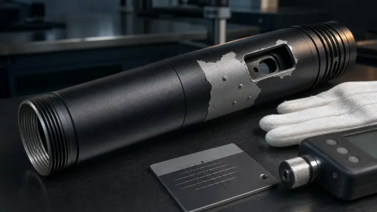
Steel can provide useful stiffness and forming behavior, but corrosion protection depends on complete and durable coverage. Cut edges, welds, crimped joints, and damaged coating deserve particular attention. If a decorative finish is applied after assembly, verify that it does not bridge fine openings or leave shadowed areas untreated.
Stainless steel
Stainless steel may reduce dependence on a decorative coating for corrosion resistance, but alloy, wire condition, forming, welding, appearance, and cost still need review. “Stainless” is not a complete material callout; the grade and finish should be defined where they matter.
Aluminum
Aluminum offers low mass and several finish options, but the selected alloy and construction must support the required mesh or perforated geometry, joining method, impact behavior, and electrical interface. If anodizing or another insulating finish is used, grounding contact areas may need a deliberate design.
For products distributed or used in Southeast Asia, discuss humid storage, condensation, perspiration, cosmetics, cleaning agents, and coastal exposure where relevant. Do not substitute a vague “tropical proof” label for agreed conditioning, test method, inspection area, and acceptance criteria.
Design the Grille for Manufacturing and Assembly
The 3D shape should be reviewed together with the intended construction route. A spherical ball grille, cylindrical studio headbasket, die-cast frame with mesh inserts, and perforated shell all create different tooling, joining, finishing, and inspection requirements.
Geometry and forming
Deep shapes can stretch or distort mesh, changing the opening geometry from the crown to the lower edge. A visually regular flat mesh may become uneven after forming. Specify where opening uniformity matters and how the formed part will be judged.
Avoid unsupported knife edges and unclear trim lines. Define radii, seam location, overlap, collar engagement, and any keep-out zone needed around a capsule or shock mount. If the grille has a front orientation, include an assembly datum so the seam or cosmetic feature does not rotate into view.
Joining and retention
Welds, brazed joints, crimps, adhesives, and mechanical locks each introduce different risks. Buyers should define whether the joint may be visible, whether discoloration is acceptable before finishing, and what pull, torque, vibration, or repeated-service check is required.
Internal foam must also be retained consistently. Loose foam can move toward the capsule; excessive adhesive can block openings or become visible; uneven compression can change the acoustic path. Define the foam position and retention method rather than leaving it as an assembly-line judgment.
Threads and mating interfaces
A removable microphone head grille needs controlled fit with the body. Drawings should identify thread standard, tolerance, coating allowance, seating face, runout, axial position, torque or hand-feel requirement, and the number of assembly cycles to validate. Review the mating part at the same time; inspecting the grille thread alone cannot reveal a stack-up problem.
Grounding and shielding continuity
When the grille is intended to contribute to electromagnetic shielding, electrical continuity across mesh, collar, thread, and main housing must be designed rather than assumed. Paint, anodizing, adhesive, contamination, or a loose joint can interrupt the path. Define contact locations and a resistance or continuity check appropriate to the microphone's electrical design. For broader system considerations, see Micbody's EMI/RFI shielding design guide for microphone internal structures.
Build a Prototype Validation Plan Before Tooling Approval
A useful grille-development sequence separates the variables instead of changing mesh, foam, geometry, and finish at once.
- Freeze the reference architecture. Confirm capsule, mount, grille envelope, cavity, body interface, and target appearance.
- Screen material stacks. Compare a small number of documented mesh and foam constructions.
- Build formed prototypes. Use the intended layer order, seam, collar, and capsule spacing.
- Run acoustic comparisons. Measure the assembled microphone against the approved reference.
- Run mechanical and use checks. Evaluate drop behavior, deformation clearance, thread cycles, foam retention, cleaning, and corrosion exposure as required.
- Approve a golden sample and controlled specification. Record materials, dimensions, construction, finish, and inspection method.
- Repeat critical checks on production-representative parts. Tooling, forming, welding, finishing, and assembly can introduce variation not present in handmade samples.
Before starting a dedicated tool, align this plan with the broader questions in Five Key Questions to Confirm Before Tooling a Microphone Housing.
What to Include in a Custom Microphone Grille RFQ
Send enough information for suppliers to quote the same part and identify risks before sampling:
- Grille assembly 2D drawing and 3D model
- Mating microphone-body drawing or physical sample
- Intended capsule, mount, and minimum internal clearances
- Outer-shell, mesh, collar, foam, fabric, and membrane material requirements
- Mesh construction, opening, wire diameter, layer count, orientation, and open-area requirement
- Overall dimensions, roundness, runout, seam position, and assembly datums
- Thread or attachment specification, coating allowance, torque, and service-cycle requirement
- Joining and internal-layer retention requirements
- Grounding or electrical-continuity requirement where applicable
- Finish, color, gloss, texture, and Class-A surface definition
- Acceptable limits for dents, loose wires, sharp edges, blocked openings, weld marks, discoloration, and mesh distortion
- Acoustic comparison method and approved reference microphone
- Drop, deformation, corrosion, perspiration, cleaner, or humidity checks relevant to the product
- Sample quantity, golden-sample process, inspection report, packaging, and change-control expectations
- Forecast quantities by prototype, pilot, and production stage
If the design is not frozen, identify which items are targets and which are mandatory. That distinction lets the supplier propose manufacturable options without quietly changing an acoustic or safety-critical requirement.
Specify the Grille as Part of the Complete Housing
A successful custom microphone grille balances sound transmission, airflow control, impact protection, appearance, shielding, serviceability, and production consistency. Those decisions cannot be completed from a mesh catalog alone. They require the capsule, internal layers, cavity, body interface, finish, assembly process, and validation plan to be considered together.
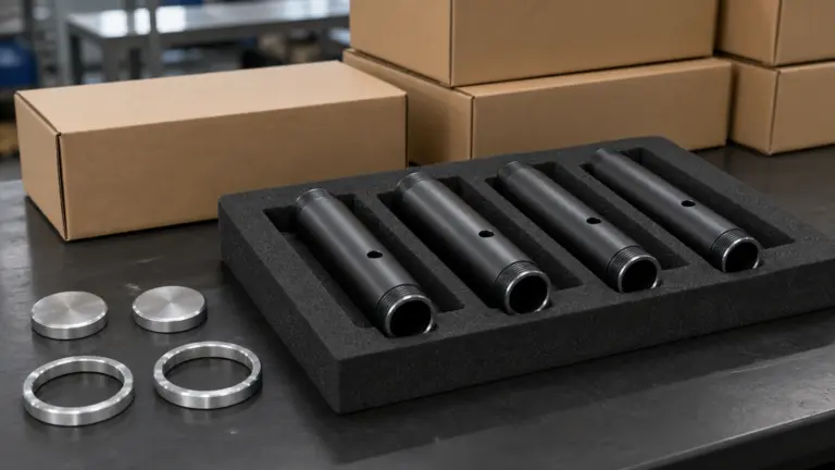
Micbody manufactures custom microphone housings and metal-component sets, including body tubes, grille heads, end caps, battery compartments, decorative rings, and switch components. Send your 2D/3D files or physical sample, mating-part information, target finish, expected quantities, and acceptance requirements for a quotation. If acoustic characteristics are critical, include the intended capsule assembly and approved reference so the grille can be developed around measurable product requirements.
FAQ
Does a microphone grille affect frequency response?
Yes. Mesh, foam, cavity geometry, spacing, blocked area, and the capsule itself interact in the acoustic path. The effect cannot be predicted reliably from open area alone, so the final grille should be validated on the assembled microphone against an approved reference.
Is a higher mesh open area always better?
No. Higher open area may reduce obstruction, but it can require thinner wire or larger openings that change strength, particle protection, forming behavior, and appearance. Layer count, foam, cavity, and local supports also affect performance. Select the complete construction against acoustic and mechanical requirements.
Is stainless steel the best material for every microphone grille?
No single metal is best for every design. Stainless steel, plated steel, and aluminum offer different forming, strength, weight, corrosion, finish, joining, grounding, and cost characteristics. The correct choice depends on the grille geometry and the finished microphone's requirements.
What files should I send to a custom microphone grille manufacturer?
Send the grille's 2D and 3D files, the mating housing and capsule-envelope information, layer construction, finish, attachment details, target quantities, approved reference, and test criteria. A physical assembly sample is also useful when thread feel, seam orientation, internal spacing, or acoustic comparison is important.